Print Friendly Version of this pagePrint Get a PDF version of this webpagePDF

Saturday 31 August 2013

Raw Material Used in Rotor Spinning

Raw Material Used in Rotor Spinning:
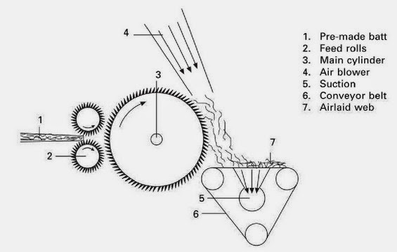
Short staple spinning m/c (up to 60 mm fiber length) require

  •  Cotton (CO)
  •  Cotton waste ( secondary m/t recycled m/t)
  •  Cotton noil
  •  Blends of two or more of these materials.
  •  Polyester fibers (PES).
  •  Polyacrylonitrile fiber ( PAC)
  •  Poly amide fiber (PA)
  •  Viscose (CA)
  •  Blends of man-made fibers ( mostly PES/ CV & PAC/CV)
  •  Blends of cotton & man made fibers ( mostly CO/ PES & CO/CV)
Important Fiber Attributes in Rotor Spinning:
  • Fiber strength
  • Fiber fineness (optimum fiber fineness)
  • Short fiber content
  • Variation in fiber length
  • Fiber to metal friction
  • Residual trash and dust content
Raw Material Requirement:
Fiber Length:
Following m/t can be processed according to Reiter Company

Cotton:

  •  Waste <7/8 inches ( for yarns up to 15 tex count)
  •  Short-staple cotton < 1 inch ( for yarns up to 30 tex count )
  •  Medium staple cotton < 1 1/8 inches (for yarn up to 17 tex count )
Man made fibers:-
  •  Staple length up to 60 mm for count = 12 tex yarns
Fiber Fineness: Finer fibers preferred in rotor spinning usually in the range of
  •  Cotton 2.8 to 4.5 micronaire.
  •  Man- made fibers 1, 1.2 to 1.7 dtex.
Coarse fibers lead to deterioration in spinning conditions; this necessitates the use of higher twist co-efficient.

Fiber Strength: Due to poorer exploitation of the fiber substance, fibers of the greatest possible strength .

Dirt & Dust: The rotor-spinning machine reacts very sensitively to the trash content of cotton. Coarse particles such as husk particles stay caught in the rotor groove. They can prevent yarn formation at this point, & this in turn can lead to an end down or to fiber agglomeration at the particle. This gives a thick place at the agglomeration point & immediately a thin place after this. More trash content also lead to more NEP generation. Small particles also lead to deterioration in quality.

Clean raw m/t is therefore a precondition for spinning of yarn on the rotor spinning m/c. in accordance with recommendations from Reiter, the following residual trash content should not be exceeded in the feed sliver:

  •  Up to Ne 6 : 0.3%
  •  Up to Ne20 : 0.2%
  •  Up to Ne 30 : 0.15%
  •  Up to Ne 50 : 0.10%
Other Foreign Matter:
  •  Quartz & mineral dust present in cotton causes wear & tear in m/c
  •  Foreign fibers lead to ends down.
  •  Honey dew makes fiber to stick to m/c parts & cotton free of honey-due should be used.
  •  Spin finish should be taken off before feeding to m/c. it acts same as honey due.
  •  Remnants of the yarn lead to thick places in the yarn, so they should not be used. 

What Is Rotor Principle of Rotor

The Rotor:
The rotor is the main spinning element of the rotor-spinning m/c. Yarn quality ,character working performance of yarn productivity, & costs etc. all depend chiefly on the rotor. The most important parameters of the rotor that exert influence are
  •  The rotor form
  •  The groove
  •  The rotor diameter
  •  Rotational speed along with
  •  The rotor bearing
  •  Co-efficient of friction b/w the fiber & the rotor wall.
  •  The air-flow conditions inside the rotor
  •  Liability to fouling
Rotors are replaceable element in the m/c.

Tasks of the Rotor Spinning Machine: The basic tasks of the rotor spinning machine are

  •  Opening (& attenuating) almost to individual fibers (fiber separation).
  •  Cleaning.
  •  Homogenizing through back doubling.
  •  Combining i.e. forming a coherent linear strand from individual fibers.
  •  Ordering (the fibers in the strand must have an orientation as far as possible in the longitudinal direction).
  •  Improving evenness through back-doubling.
  •  Imparting strength by twisting
  •  Winding.
Principle of Rotor Spinning:The general principle of rotor spinning is shown in Figure. The input fiber strand is a drawn sliver. A sliver may have more than 20,000 fibers in its cross-section. This means that a yarn of 100 fibers per cross-section will require a total draft of 200. This amount of draft is substantially higher than that of ring spinning. Drafting in rotor spinning is accomplished using a comber roll (mechanical draft) which opens the input sliver followed by an air stream (air draft). These two operations produce an amount of draft that is high enough to reduce the 20,000 fibers entering the comber roll down to few fibers (5-10 fibers). In order to produce a yarn of about 100 fibers per cross-section, the groups of few fibers emerging from the air duct are deposited on the internal wall of the rotor and a fiber ring is formed inside the rotor.

The total draft in rotor spinning is, therefore a combination of true draft from the feed roll to the rotor (in the order of thousands) and a condensation to accumulate the fiber groups into a fiber ring inside the rotor. The total draft ratio is the ratio between the delivery or the take-up speed and the feed roll speed. This should approximately amount to the ratio between the number of fibers in the sliver cross-section and the number of fibers in the yarn cross-section. 

Rotor Spinning process
Consolidation in rotor spinning is achieved by mechanical twisting. The torque generating the twist in the yarn is applied by the rotation of the rotor with respect to the point of the yarn contacting the rotor navel. The amount of twist (turns per inch) is determined by the ratio between the rotor speed (rpm) and the take up speed (inch/min). Every turn of the rotor produces a turn of twist, and a removal of a length of yarn of 1/tpi inches.

The winding operation in rotor spinning is completely separate from the drafting and the twisting operations. The only condition here is that the yarn is taken up at a constant rate. This separation between winding and twisting allows the formation of larger yarn packages than those in ring spinning.

Sequence of Operation:The feed stock in form of either card sliver or draw frame sliver from first or second passage drawing. The sliver runs from a can beneath the spinning unit into the feed trumpet. A feed roller grips the sliver & pushes it over the feed through into the region of the opening roller. A spring ensures firm clamping of the sliver by urging the trough towards feed roller. In the event of an end-break, the feed unit is stopped either by stopping the feed roller rotation or by pivoting the in feed trumpet, in each case sliver feed stops automatically. The signal pulse causing this effect is generated by a yarn-sensing arm.

In the in conventional spinning processes, the fiber strand at in feed is maintained as a coherent structure & is merely attenuated during spinning. In rotor spinning, the fiber strand is opened to individual fibers. This task is performed mainly by the opening roller. This small roller which is clothed with needles or saw teeth, combs through the fiber beard projecting from the nip between the feed roller & the tough it transports the plucked fibers to the feed tube. An air flow is needed for further transport of the fibers to the rotor. This is generated by central fan that draws air by suction through leads from each rotor box. To facilitate generation of this under pressure, the rotor box must be hermetically sealed as far as possible. The suction stream in the feed tube lifts the fibers off the surface of the opening roller & leads them to the rotor. In the course of this movement, both the air & the fibers are accelerated because of the convergent form of the feed tubes. This represents a second draft following the nip trough/ opening roller & giving further separation of the fibers. Moreover partial straightening of the fibers is achieved in this air flow. A third draft arises upon arrival of the fibers on the wall of the rotor because the peripheral speed of the rotor is several times as the speed of the fiber. This is a very important feature because it contributes significantly to good orientation of the fibers. The last straightening of the fibers occurs as the fiber slides down the rotor wall into the groove under the influence of the enormous centrifugal forces work within the rotor.

Speed Interrelationship: Normal & maximum revolutions & speeds are

  •  Rpm of opening roller :5000 -10000 rpm
  •  Rpm of rotor up to 100000 rpm
  •  Delivery speed: up to 200m/min.
Technical Data of Rotor Spinning Machine:
  •  Number of spinning positions per m/c           up to 220
  •  Count range                                                12- 125 Tex (5 – 50 Ne)
  •  Draft                                                           25- 400
  •  Speed of rotation of opening roller               6000- 11000 rpm
  •  Rotation speed of rotor                                up tp 120000 rpm
  •  Rotor diameter                                            32 -65 mm
  •  Delivery speed ( m/ min)                              up to 200
  •  Package mass                                             up to 5 kg
  •  Angle of taper                                             2° - 4° 20’
  •  Winding angle                                             29° – 45° 

Different Types of Yarn Spinning System

Spinning:
The present participle of the verb 'to spin' used verbally, adjectivally, or as a noun, meaning process or the processes used in the production of yarns or filaments.

The term may apply to: (i) The drafting and, where appropriate, the insertion of twist in natural or staple man-made fibres to form a yarn;
(ii) The extrusion of filaments by spiders or silkworms; or
(iii) The production of filaments from glass, metals, fibre-forming polymers or ceramics.

Ring spinning
In the spinning of man-made filaments, fibre-forming substances in the plastic or molten state, or in solution, are forced through the holes of a spinneret or die at a controlled rate. There are five general methods of spinning man-made filaments i.e. dispersion spinning, dry spinning, melt spinning, reaction spinning, and wet spinning, but combinations of these methods may be used.

In the bast and leaf-fiber industries, the terms 'wet spinning' and 'dry spinning' refer to the spinning of fibres into yarns in the wet state and in the dry state respectively.

Open-end Spinning;
Break Spinning:
A spinning system in which sliver feed stock is highly drafted, ideally to individual fibre state, and thus creates an open end or break in the fibre flow. The fibres are subsequently assembled on the end of a rotating yarn and twisted in. Various techniques are available for collecting and twisting the fibres into a yarn, the most noteworthy being rotor spinning and friction spinning.

Rotor Spinning:
A method of open-end spinning which uses a rotor (a high-speed centrifuge) to collect individual fibres into a yarn is known as Rotor spinning. The fibers on entering a rapidly rotating rotor are distributed around its circumference and temporarily held there by centrifugal force. The yarn is withdrawn from the rotor wall and, because of the rotation, twist is generated.

Friction Spinning:
A method of open-end spinning which uses the external surface of two rotating rollers to collect and twist individual fibres into a yarn is known as Friction spinning. At least one of the rollers is perforated so that air can be drawn through its surface to facilitate fibre collection. The twisting occurs near the nip of the rollers and, because of the relatively large difference between the yam and roller diameters, high yarn rotational speeds are achieved by the friction between the roller surface and the yarns.

Air-jet Spinning:
A system of staple-fibre spinning which utilizes air to apply the twisting couple to the yarn during its formation is known as Air-jet spinning. The air is blown through small holes arranged tangentially to the yarn surface and this causes the yarn to rotate. The majority of systems using this technique produce fasciated yarns, but by using two air jets operating in opposing twist directions it is possible to produce yarns with more controlled properties but of more complex structure.

Centrifugal Spinning:
A method of man-made fiber production in which the molten or dissolved polymer is thrown centrifugally in fibre form from the edge of a surface rotating at high speed. The term is also used to describe a method of yarn formation involving a rotating cylindrical container, in which, the yarn passes down a central guide tube and is then carried by centrifugal force to the inside of a rotating cylindrical container.

Dispersion Spinning:
A process in which the polymers that tend to an infusible, insoluble, and generally intractable character (e.g., polytetrafluoroethylene) are dispersed as fine particles in a carrier such as sodium alginate or sodium xanthate solutions is known as Dispersion spinning. These permit extrusion into fibers, after which the dispersed polymer is caused to coalesce by a heating process, the carrier being removed either by heating or by a dissolving process.

Draw-Spinning:
A process for spinning partially or highly oriented filaments in which the orientation is introduced prior to the first forwarding or collecting device.

Dry Spinning (man-made fiber production):
The spinning process involving conversion of a dissolved polymer into filaments by extrusion and evaporation of the solvent from the extrudate is known as Dry spinning.

Flash Spinning:
A modification of the accepted dry-spinning method in which a solution of a polymer is extruded at a temperature well above the boiling point of the solvent such that on emerging from the spinneret evaporation occurs so rapidly that the individual filaments are disrupted into a highly fibrillar form.

Flyer Spinning:
A spinning system in which yarn passes through a revolving flyer leg guide on to the package is known as Flyer spinning. The yarn is wound-on by making the flyer and spinning package rotate at slightly different speeds.

Melt Spinning (man-made fiber production):
The spinning process involving conversion of a molten polymer into filaments by extrusion and subsequent cooling of the extrude is known as Melt spinning.

Reaction Spinning (man-made-fiber production):
A process in which polymerization is achieved during the extrusion of reactants through a spinneret system.

Ring Spinning:
A spinning system in which twist is inserted in a yarn by using a revolving traveller is known as Ring spinning. The yarn is wound on since the rotational speed of the package is greater than that of the traveller.

Wet Spinning (man-made-fiber production):
The spinning process involving conversion of a dissolved polymer into filaments by extrusion into a coagulating liquid is known as Wet spinning. The extrusion may be directly into the coagulating liquid or through a small air-gap. In the latter case it may be known as dry-jet wet spinning or air-gap wet spinning.

Airlaid Web Formation Technique


PRINCIPLE OF WEB FORMATION IN A SIMPLE AIR LAYING PROCESS:
RAW MATERIAL: 
  • Natural or man-made textile fibre (cut length >25 mm)
  • Short cut fibres (generally <25 mm)
  • Wood pulp (1.5–6 mm)
Air laid fabric compared with carding technology has these features: 
  • The fibers are oriented randomly on the fabric surface – isotropic structure.
  • Voluminious webs can be produced
  • The range of the area weight is wider (15 – 250 g/m2) but the mass uniformity of light air laid (up to 30 g/m2) is bad.
  • Wide variety of processable fibers
AIR LAID – PRODUCTION PROBLEMS: 
  • Low level of opening fiber material by lickerin roller Thus is suitable to use pre-opened fibers or combine air laid with card machine – Random card machine.
  • Variable structures of web in width of layer due to irregular air flow close to walls of duct . This problem requires high quality design of duct. 
  • Possible entangling of fibers in air stream. This problem can be reduced by increasing the ratio air/fibers which nevertheless means decrease in performance and increase of energy consumption due to high volume of flowing air.
The relation between air flow and performance of device shows the importance of fiber length and fiber diameter. QA is air flow, K is device constant, P is performance of device (kg/hour), L is lenght of fiber staple (m) and D is fiber fineness (dtex).
QA = K.P.L2/D

Thus is suitable to use short fibers for this technology.


Random cards – combination of air laid and carding technology:
A major objective of this combination is isotropic textile fabric (random orientation of fibers) with good mass uniformity of light fabrics and with high production speed. 
  • The first part – card machine opens perfectly fibrous material so single fibers are as a output.
  • The second part – air laid system uses the centrifugal force to strip the fibers off a roller and. put them down on an air controlled scrim belt.
Main variations of random cards I. Airlaid function of random card:
1) Random roller between main cylinder and doffer, which rotate in the opposite direction of the main cylinder.

MAIN VARIATIONS OF RANDOM CARDS:

Main variations of random cards II:
2) Centrifugal force of mean cylinder strips the fibers off.

AIR LAID AND RANDOM CARDS: USED FIBERS: 

Synthetic fibres, viscose, cotton and blends thereof; natural fibres such as flax, hemp, sisal etc.; Reclaimed textile waste and shoddy, cellulose pulp 1.7 - 2000dtex. Max. 120 mm staple length

FEEDING SYSTEM OF RANDO WEBBER:

RANDO-WEBBER SYSTEMS WITH PERFORATED SCREEN:
RANDO-WEBBER SYSTEMS WITH CYLINDRICAL CONDENSERS:
Rando-webber:
  • Relatively narrow widths up to about two metres
  • Webs of 10– 3000 g/m 2
  • Virgin or recycled fibres
  • Filtration, home furnishings, automotive fabrics, insulation and some medical specialities
RANDOM CARD K12 OF DR. E. FEHRER:
HIGH-PRODUCTION RANDOM CARD K21 OF DR. E. FEHRER:
  • K12 is more particularly suited to coarse fibres (10–110 dtex), Basic weight range 20– 2000 g/m 2
  • K21 is more particularly suited to synthetic and viscose rayon fibers of (1.7–3.3 dtex), Basic weight range 10–100 g/m 2
SCHEMATIC VIEW OF THE DOA AIRLAYING SYSTEM:
SCHEMATIC VIEW OF THE AIR LAYING SYSTEM:
CHICOPEE AIRLAYING SYSTEM:
  • Air velocity ( 140 m/s)
  • Surface speed of the cylinder ( 20–60 m/s)
  • Staple fibres ranging from 13–75 mm
SPINNBAU AIRLAYING SYSTEM:
THIBEAU HYBRID CARD AIRLAYING MACHINE:
Thibeau hybrid system: 
  • Typical MD/CD ratio of 1.2–1.5:1
  • Production rate of 200–260 kg/h/m
  • Web weights of 35–200 g/m 2
  • Fibre types cotton, viscose rayon, PET, PP, PA
  • Fibre length of 10–40 mm.
“TURBO-UNIT”
TURBO-CARD RC 2-6 TR:
Turbo-Unit and Turbo-Card: 
  • The turbo-unit TU is either fed by pre-carded webs via a feed plate intake or may be combined with a random card.
  • The turbo-roll is equipped with carding segments.
  • Aerodynamical web-forming by centrifugal force, doffer fan and suction conveyor
  • Lower to medium fibre fineness range
  • Staple length: approx. 10 - 80 mm
  • Web weight: approx. 25 - 450 g/m 2
  • Throughput depending on fibre fineness and fibre type: up to approx. 400 kg/h/m of working width
  • Working widths: up to 4.000 mm
  • Web speed: approx. 20 - 120 m/min
WEB FORMING MACHINE 008-0445 OF LAROCHE S.A.:
Laroche System: 
  • Web weight ranges from 300 to 3000 g/m 2
  • Production speed of up to 10–15 m/min
  • Fibre length should be in the range 20–75 mm
  • Cotton, man-made, glass fibres
  • Hemp, flax, sisal, coconut
  • Bed covers, mats, upholstery and insulation material, carrier material for carpets, industrial and geotextiles as well as furniture textiles
GENERAL PROPERTIES OF AIRLAID FABRICS: 
  • HIGH ISOTROPICITY
  • HIGH LOFT (IF REQUIRED)
  • HIGH POROSITY (95–>99%)
  • HIGH ABSORBENCY AND WICKING RATE
  • SOFT HANDLE
  • ADEQUATE TENSILE STRENGTH
  • GOOD RESILIENCY (COMPRESSION RECOVERY)
  • HIGH THERMAL RESISTANCE.
Air laid and random cards: end products:
  • Chemical bonding: napkins, table cloths and wipes
  • Thermal bonding: nappies (different components, i.e., acquisition layer, distribution layer and absorption core), feminine hygiene/incontinence products and insulation
  • Spunlacing: wet and dry wipes for domestic and industrial applications medical textiles (including disposable gowns, curtains, wound-care dressings, bed sheets), filtration media
  • Needle punching: interlinings and shoe linings, wadding, medical and hygiene products, geotextiles and roofing felts, insulation felts, automotive components, filters, wipes
Combination of unidirectional and cross directional web:

CROSSLAPPER WITH HORIZONTAL LAYING DEVICE:
Tasks of the web-laying machine:
  • Increasing the web mass
  • Increasing the web width
  • Determining the web strength in the length and cross directions
  • Improving the end product quality
LAP DRAFTER VSTG:
WORKING WIDTH UP TO 7.000 MM. INDIVIDUAL SERVO-DRIVES FOR 4 DRAFTING ZONES WITH INFINITELY VARIABLE DRAFTS. ONLY LITTLE CHANGES OF BATT WEIGHT REGULARITY BY FIBRE RE-ORIENTATION INCREASE STRENGTH IN MD.
MERITS AND LIMITATIONS OF CARD – CROSS LAPPING AND AIR LAYING:

3D Weaving Manufacturing Process of 3D

3D-Weaving:
3D-Weaving is a complete new concept in case of weaving. The first method of 3D woven fabric denotes 3 Dimensional fabrics, that is length, width and breadth. In 3 Dimensional fabrics, the thickness is an important criterion. Ordinary fabrics also have length, width and breadth, but in the 3 Dimensional fabrics, the thickness is much more than ordinary fabric. The thickness is achieved by forming multiplayer using multi series of warp and multi series of weft, which are intersecting at regular 90o angle as in usual cloth weaving principle.

It cannot be performed with existing traditional methods and machines. It interlaces a multiple layer warp with multiple horizontal wefts and multiple vertical wefts producing directly shell, solid and tubular types of fully interlaced 3D fabrics with countless cross-sectional profiles.

First demonstrated in 1997, Dual-Directional (D-D) Shedding System is indispensable for performing 3D-weaving. This path breaking development has advanced the technology of weaving to a new dimension for the first time in its more than 27000 years of history.

Manufacturing Technology of 3D-Weaving:

Special looms are required to operate the warp threads in 60o angle for weaving 3Dr-3 Directional fabrics. But the 3 Dimensional -3Dm- fabric can be woven by using ordinary loom with usual weaving principle-shedding, picking, beating - by having multi layers of warp and multi layers of weft. Even though the treble cloth with 3 series of warp and weft could be called 3Dm fabrics, in general, minimum 4 series of warp and weft are used in weaving to form several layers, one above the other to get the sufficient thickness resulting into 3 Dimensional fabric.
As per the principle of weft Tapestry fabric, to weave 3Dm fabrics, it is required to use one series of stitching warp and multi series of separating warp as per the number of layers to be formed. 

 As seen from the cross section, the stitching warp passes from top to bottom and bottom to top but all the separating warp lies almost straight and hence the stitching warp takes up more length than the separating warp. Therefore, the stitching warp is brought from a loose tension beam and the entire separating warp is brought from another normal tension beam.

The following points are to be understood from both the cross sections: -

The first layer weft (Face) - shown as "a" - lies between the stitching warp (shown as 1) and first separating warp series (shown as 3).
The second layer of weft (Middle) - shown as "b"- lies between the first and second separating warp series (shown as 3 and 4).
Application of 3D Weaving Fabric:

A new method has been developed for the manufacture of bifurcated prosthesis used in medical applications and they are used to replace the defective blood vessels in patients so as to improve blood circulation.

The 3D fabrics have recently entered the medical field. Their specific area of application is in the weaving of vascular prosthesis. Vascular prosthesis are surgically implantable materials. They are used to replace the defective blood vessels in patients so as to improve blood circulation. Conventional types of prosthesis were made from air corps parachute cloth, vignon sailcloth, and other types of clothing materials.

Materials such as nylon, Teflon, orlon, stainless steel, glass, and Dacron polyester fibre have been found to be highly suitable for the manufacture of prosthesis. These materials were found to be significantly stable with regard to resistance to degradation, strength, and were not adversely affected by other factors. Dacron polyester, which has bio-compatibility and high tensile strength, is being used over a period of time as suture thread or artificial ligaments.

Wednesday 28 August 2013

Jute Products Manufacturing Process

Jute Fiber:
Jute fiber is a natural bast fiber. It is one of the most affordable natural fibers and is second only to cotton in amount produced and variety of uses of vegetable fibers. It is harder than other textile fibers. It is environment friendly. Normally jute are used for sacking, burlap, and twine as a backing material for tufted carpets. 
Jute plant
Chemical Composition of Jute: 
Jute is composed of 65% cellulose and 35% natural wages, oils and cements (lignin).

The chemical composition of jute is given below: 

  • Cellulose....................................... 65.2%
  • Hemicelluloses ...............................22.2%
  • Lignin ............................................10.8%
  • Water soluble ................................1.5%
  • Fat and wax ..................................0.3 - 1.0%
Classification of Jute: In accordance with color jute is two types 
  1. White jute (Corchorus capsularis)
  2. Tossa jute (Corchorus olitorius)
Classification of jute according to the quality (Geographical distribution according to Bangladesh): 
  1. Jat
  2. District
  3. Northern
Common Defects Found in Jute: Specky Jute:If the Jute Fibers are not rotted and washed properly; the barks of jute adhere to the fibers and causes them speck. Speck in jute is a major defect of jute which lowers the quality of Jute fibers.
Defect in jute
Rooty Jute: 
This kind of Jute Defects occurs due to various reasons such as under retting of the root ends of Jute fibers and if the root portion is not completely under water during ratting.

Croppy Jute: 
If the top end of the fibers is rough, black and hard then stripping is insufficient which causes croppy jute.

Knotty Jute: 
This kind of knotty jute defects is caused by insect bite in the jute plants.

Hunka: 
This type of Jute is hard and barky caused by insufficient removal of hard bark from jute.

Mossy Jute: 
Mossy grows in stagnant of water. The mosses adhere to the Jute fibers causing Mossy Jute.

Glossy Jute:
 
Highly lustrous jute fiber sometimes creates problems. This kind of highly lustrous jute fiber is named as Glossy Jute.

Flabby Jute: 
Hairy Jute fiber defects are created due to over retting and careless stripping of Jute.

Runners: 
Long hard and broken ribbon like fibers caused careless stripping and washing.

Dazed Jute Fibers: 
The Jute fibre which has lost it’s strength and luster due to over retting or excessive moisture in it.

Heart Damage: 
This kind of defects caused for badly damage rotten or tendered fibers.

Weak fibers: 
Over retting is the main cause of weak fibers, also due to under drying and sorting in moist condition.

Sticky or Woody: 
In the top end at the jute plant is not stripped properly from the fiber, the brow pieces of the plant remain the fiber ceurecl this defect. It is due to over retting of lower part of the plant is under retting of lower part of the plant is under retting of the top end.

Flow Chart of Jute Spinning:

 Due to its worldwide demand different country manufacture jute goods. Jute goods produce by a line of sequence. Its manufacturing process is completely different from cotton. By the following way jute goods are produced: 

Selection of jute for a batch
                                       ↓ 
(According to jute grade) 
Piecing up

Softening or Lubricating
                                               ↓ 
(Application of emulsion on jute) 
Conditioning or Piling
                                           ↓ 
(Piling of jute for certain time) 
Breaker Card
                                                       ↓ 
(Inter Card is used between this two) 
Finisher Card
                                            ↓ 
(It may be half or full circular) 
First Drawing Frame

Second Drawing Frame

Third or Finisher Drawing Frame

Jute spinning

Winding

Beaming

Weaving

Dumping

Calendering

Lapping

Cutting

Hemming

Herackele sewing

Bailing

Export


Selection: 
In the selection process, raw jute bales are opened to find out any defect and to remove the defective portion from the mora by experienced workers. Raw jute bales are of two types i.e. 150 kg weight and 180 kg weight with or without top portion cutting. 


The bales are assorted according to end use like Hessiean weft, Sacking wrap, Sacking weft etc. After selection, jute bales are carried to softning section by workers called Gariwala and Bajawala.

Batch & Batching 
A number of bales of jute selected for the purpose of manufacturing a particular type of yarn in known as batch.

Batching cover all the process preparatory to carding. The main purpose of batching is to add oil and water to make the jute fiber flexible, soft and stiff free.

Softening 
In softening process jute morahs are made soft and pliable. Two methods are used for softening; use of softening machine and use of jute good spreader. Generally an emulsion plant with jute softener machine is used to lubricate and soften the bark and gummy raw jute. The emulsion plant consists of gear pump, motor, vat, jet sprayer, nozzles, emulsion tank and the jacket. In this softening process jute becomes soft and pliable and suitable for carding.

Conditioning or Piling and Pile Breaking Conditioning or piling refers to the rest stage, in which jute is given after the water and oil have been applied. It lasts longer with low grade batching to allow the hard barky root material to become softened before passing on the cards.

The main function of pile breaker is to break the pile and serve it to the carding machines. The softener machine output material carried by pilemen through bile to the pile place for pilling. During piling superficial moisture penetrates inside Fiber and "Thermo fillic" action take place which softener the hard portion of the root. After piling for nearly 24 hours the pile breakers carry the material to the carding machine.

Jute Carding 
The process by which long reeds of jute while passing through high speed pinned roller and broken down into an entangled mass and delivered in the form of ribbon uniform weight per unit length called jute carding.

There are three different carding sections: 

  1. breaker carding
  2. inner carding
  3. finisher carding
Breaker Carding 
In the Breaker carding machine soften jute after piling is feed by hand in suitable weight. The machine by action with different rollers turns out raw jute in the form of jute sliver for finisher carding. In this process root cutting is necessary before feeding the material to the hand feed breaker carding machine.

Finisher Carding Finisher carding machine make the sliver more uniform and regular in length and weight obtained from the Breaker carding machine. Finisher carding machine is identical to the Breaker carding machine, having more pair of rollers, staves, pinning arrangement and speed. Nearly 4 to 12 slivers obtained from Breaker carding machine is fed on this machine. The material thus obtained is send to drawing section.

Jute Drawing: 
Drawing is a process for reducing sliver width and thickness by simultaneously mixing 4 to 6 sliver together. There are three types of Drawing Frame machine. In most mills 3 Drawing passages are used in Hessian and 2 Drawing passages are used in Sacking.

First Drawing The slivers obtained from finisher carding machine is fed with four slivers on to the first drawing frame machine. The first drawing frame machines makes blending, equalising the sliver and doubling two or more slivers, level and provide quality and color. This machines includes delivery roller, pressing roller, retaining roller, faller screw sliders, check spring, back spring, crimpling box etc..

Second Drawing In second drawing, the Second Drawing Frame machine obtain the sliver from the First drawing machine and use six slivers and deliveries per head. The Second Drawing machine makes more uniform sliver and reduce the jute into a suitable size for third drawing.

Third Drawing 
In the third drawing, the Third Drawing frame machine uses the sliver from second drawing. The Third Drawing machine is of high speed makes the sliver more crimpled
and suitable for spinning.

Jute Spinning: Spinning is the process for producing yarn from sliver obtained from Third drawing. The jute spinning frame machine is fitted with slip draft zone and capable of producing quality yarns at high efficiency with auto-doffing arrangements also.


Winding : 
Winding is a process which provides yarn as spools and cops for the requirement of beaming and weaving operations. There are two types of winding : 
  1. Spool Winding
  2. Cope Winding
Spool Winding 
In Spool Winding yarn is produces for warp (the longitudinal yarn). Spool winding machine consists of a number of spindles. There is wide variation in the number of spindles per machines from one make to another. Productivity of spool winding depends on the surface speed of the spindle and machine utilisation. 

Spool winding machine uses the bobbins contain smaller length of yarn. This machine wound the yarn into bigger packages known as 'spool'. The Spool are used in making sheets of yarn to form warp portion used during interleecment of weaving. 

Cop Winding 
Cop Winding machine obtain yarns from the spinning machines. The spinning bobbins is placed on a suitable pin on top of the cop machine and yarn tension is maintained by means of a small leaver. The yarn on the bobbins are cnverted into hollow cylindrical package said to be cop. The cop is used to form Transverse thread during interlacement of weaving. Generally a cop winding machines consist 120 spindles. 

Beaming : 
Beaming process is follows after spool winding. In Beaming operation yarn from spool is wounded over a beam of proper width and correct number of ends to weave jute cloth. To increase the quality of woven cloth and weaving efficiency, the wrap yarns are coated with starch paste. Adequate moisture is essential in this process.

Quality characteristic of a beam is width of beam - number of ends and weight of stand and there is a continuous passage of yarn through starch solution from spools to the beam. 

Strach solution in water contains tamerine kernel powder (TKP), antiseptic - sodium silica fluride (NaSiF4) and its concentration varies with the quality of yarn. 

Weaving : 
Weaving is a process of interlacement of two series of threads called "wrap" and "weft" yarns to produce the fabric of desired quality. There are separate looms for hessian and sacking in weaving section. The Hessian looms, shuttle which contents cops (weft yarn) is manually changed. The sacking looms are equipped with eco-loader to load a cop automatically into the shuttle.

Dumping : 
Dumping is the process in which the rolled woven cloth is unrolled and water is sprinkled on it continuously to provide desired moisture. Each roll is generally104 yards or 95.976 meters. Damping is done manually. 

Calendering : 

Calendering is a process similar to ironing of fabric. After damping the damped fabric passes through pairs of heavy rollers rendering threads in fabric flattened and improve the quality and appearance. 

Lapping : 
Lapping is the process in which Hessian fabrics are folded into the required size used in "Bale press" operation on the lapping machine. 

Cutting : 
Cutting is the process where the sacking cloth is cut to the required length for making bags for different size such as A-Twill bags and B-twill bags of 100 kg capacity.

Hemming : 
In Hemming process, the raw edges of sacking cloth cut pieces are shown by folding it with sewing machine.

Herackele Sewing : In Herackele sewing the sides of sacking cloth cut pieces are shown to make a complete bag.

Bailing : Bags or Bale processing cloths are pressed compactly according to buyers need.

Export: 
Export jute a goods per buyer requirements 


Advantages and Disadvantages of Jute Fiber:
Advantages of Jute Fiber: 
  1. Jute Fiber has great antistatic properties; so that any kind of static charges are not produced during Jute Product making or using.
  2. Jute is an insulating fiber and this is why it can be used to make cloth which would be used in electrical works.
  3. Temperature is passed in this fiber slowly because of the low thermal conductivity.
  4. Moisture Regain properties is good enough (about 13.75%).
  5. Produce no irritation in skin.
  6. 100% Biodegradable; so it is environment friendly fiber like Cotton.
  7. Cheap in market.
  8. Available in the market and the overall productivity of Jute Fiber is good.
  9. Tensile strength is high.
  10. Jute Fabric is highly breathable and comfortable to use.
  11. Can be widely used in Agriculture Sector, Textile Sector, Woven Sector, Nonwoven Sector.
  12. Jute Fiber can be blended with Natural and Synthetic fibers.
  13. Can be died by Basic, Vat, Sulpher and Reactive Dyes.
Disadvantages of Jute Fiber:
  1. The crease resistance of Jute is very low.
  2. Drape Property is not good enough.
  3. Create Shade effect and becomes yellowish if sunlight is used.
  4. If Jute is wetted it loses its strength.
Uses/Applications of Jute in Textile & Practical Life: 
  1. Jute is a fiber which has almost 1000 different kind of uses. Jute has been taken as most important fiber like as cotton as it can be used in various purposes and easy to cultivate too.
  2. Jute sacks are widely used in the practical life and coarse fabric made by Jute has no substitute ever. The wrapping bales or raw cotton also made by Jute.
  3. As Jute is completely a biodegradable Fiber; it is suitable for many uses if it is replaced in so called synthetic fiber. Synthetic fiber is very unstable and sometimes impacts badly on the natural environment where Jute is quite good alternatives to use.
  4. Jute fiber can be blended with other natural and cellulosic fiber like Cotton and make a quite stable and different blended yarn which is stronger and shiner.
  5. Jute is not only used to make yarn or cloth but also it is used to make Jute Pulp and paper. As the people of the world are being so much conscious now and trying to stop the cutting wood or plants to save the nature; Jute is drastically being used as the alternative of Wood in the Paper manufacturing Industry.
  6. Jute has a bright history of use in making sackings, carpets for the households and so on, cotton bale and wrapping fabrics for that and various fabric manufacturing industry in order to make mats, curtain, brush and etc.
  7. Now a day Jute is not only being used in Textile industry; but also it is used in Automobile Industry, Furniture and bedding industry and Paper Making industry.
  8. Jute is also being blended with other fibers to make non-woven, composites and technical textiles. The nomenclature of Jute is “Wood Fiber” which is exclusively being used on the leading manufacturing industries with some promising features.
  9. By using Jute we can produce various type of fabric named Hosiery Cloth, Hessian Cloth, Sacking, Scrim, Carpet Backing Cloth, canvas etc.
  10. Hessian is lighter than sacking and is used for bags, wrappers, wall covering, geo textiles, upholstery and different home furnishing. By using the Heavy jute fibers the Sacking is to be made.
  11. Jute has diversified uses now a days. Some of the exclusive and modern use of Jute is in Espadrilles, Floor coverings, Home textiles, high performance technical textiles, geo textiles, composites, and more.
  12. Due to the strong color and light fastness properties; just is widely used in decoration of home. Jute is more durable than any other fiber because of its anti-static properties and low thermal conduction.
  13. Most importantly; Jute is a bio-degradable fiber which comes from nature and decomposed on nature too. So it’s an environment friendly fiber for the green people to access the green world

Cotton Fibre

COTTON FIBRE:


COTTON FIBRE GROWTH:

Improvements in cotton fiber properties for textiles depend on changes in the growth and development of the fiber.
  •  Manipulation of fiber perimeter has a potential to impact the length, micronaire, and strength of cotton fibers. The perimeter of the fiber is regulated by biological mechanisms that control the expansion characteristic of the cell wall and establish cell diameter.
  • Improvements in fiber quality can take many different forms. Changes in length, strength, uniformity, and fineness   In one recent analysis, fiber perimeter was shown to be the single quantitative trait of the fiber that affects all other traits . Fiber perimeter is the variable that has the greatest affect on fiber elongation and strength properties. While mature dead fibers have an elliptical morphology, living fibers have a cylindrical morphology during growth and development. Geometrically, perimeter is directly determined by diameter (perimeter = diameter × p). Thus, fiber diameter is the only variable that directly affects perimeter. For this reason, understanding the biological mechanisms that regulate fiber diameter is important for the long-term improvement of cotton.
  • A review of the literature indicates that many researchers believe diameter is established at fiber initiation and is maintained throughout the duration of fiber development . A few studies have examined, either directly or indirectly, changes in fiber diameter during development. Some studies indicate that diameter remains constant ; while others indicate that fiber diameter increases as the fiber develops.
  • The first three stages occur while the fiber is alive and actively growing. Fiber initiation involves the initial isodiametric expansion of the epidermal cell above the surface of the ovule. This stage may last only a day or so for each fiber. Because there are several waves of fiber initiation across the surface of the ovule , one may find fiber initials at any time during the first 5 or 6 d post anthesis. The elongation phase encompasses the major expansion growth phase of the fiber. Depending on genotype, this stage may last for several weeks post anthesis. During this stage of development the fiber deposits a thin, expandable primary cell wall composed of a variety of carbohydrate polymers . As the fiber approaches the end of elongation, the major phase of secondary wall synthesis starts. In cotton fiber, the secondary cell wall is composed almost exclusively of cellulose. During this stage, which lasts until the boll opens (50 to 60 d post anthesis), the cell wall becomes progressively thicker and the living protoplast decreases in volume. There is a significant overlap in the timing of the elongation and secondary wall synthesis stages. Thus, fibers are simultaneously elongating and depositing secondary cell wall.
  •  The establishment of fiber diameter is a complex process that is governed, to a certain extent, by the overall mechanism by which fibers expand. The expansion of fiber cells is governed by the same related mechanisms occurring in other walled plant cells. Most cells exhibit diffuse cell growth, in which new wall and membrane materials are added throughout the surface area of the cell. Specialized, highly elongated cells, such as root hairs and pollen tubes, expand via tip synthesis where new wall and membrane materials are added only at a specific location that becomes the growing tip of the cell. While the growth mechanisms for cotton fiber have not been fully documented, recent evidence indicates that throughout the initiation and early elongation phases of development, cotton fiber expands primarily via diffuse growth . Later in fiber development, late in cell elongation, and well into secondary cell wall synthesis (35 d post anthesis), the organization of cellular organelles is consistent with continued diffuse growth . Many cells that expand via diffuse growth exhibit increases in both cell length and diameter; but cells that exhibit tip synthesis do not exhibit increases in cell diameter . If cotton fiber expands by diffuse growth, then it is reasonable to suggest that cell diameter might increase during the cell elongation phase of development.
  •  Cell expansion is also regulated by the extensibility of the cell wall. For this reason, cell expansion most commonly occurs in cells that have only a primary cell wall . Primary cell walls contain low levels of cellulose. Production of the more rigid secondary cell wall usually signals the cessation of cell expansion. Secondary cell wall formation is often indicated by the development of wall birefringence.
  •  Analyses of fiber diameter and cell wall birefringence show that fiber diameter significantly increased as fibers grew and developed secondary cell walls. Both cotton species and all the genotypes tested exhibited similar increases in diameter; however, the specific rates of change differed. Fibers continued to increase in diameter during the secondary wall synthesis stage of development, indicating that the synthesis of secondary cell wall does not coincide with the cessation of cell expansion.

GINNING:

  • The generally recommended machinery sequence at gins for spindle-picked cotton is rock and green-boll trap, feed control, tower drier, cylinder cleaner, stick machine, tower drier, cylinder cleaner, extractor feeder, gin stand, lint cleaner, lint cleaner, and press. 
  • Cylinder cleaners use rotating spiked drums that open and clean the seedcotton by scrubbing it across a grid-rod or wire mesh screen that allows the trash to sift through. The stick machine utilizes the sling-off action of channel-type saw cylinders to extract foreign matter from the seedcotton by centrifugal force. In addition to feeding seedcotton to the gin stand, the extractor feeder cleans the cotton using the stick machine's sling-off principle. 
  • In some cases the extractor-feeder is a combination of a cylinder cleaner and an extractor.    Sometimes an impact or revolving screen cleaner is used in addition to the second cylinder cleaner. In the impact cleaner, seedcotton is conveyed across a series of revolving, serrated disks instead of the grid-rod or wire mesh screen.
  •  Lint cleaners at gins are mostly of the controlled-batt, saw type. In this cleaner a saw cylinder combs the fibers and extracts trash from the lint cotton by a combination of centrifugal force, scrubbing action between saw cylinder and grid bars, and gravity assisted by an air current 
  •  Seedcotton-type cleaners extract the large trash components from cotton. However, they have only a small influence on the cotton's grade index, visible liint foreign-matter content, and fiber length distribution when compared with the lint cleaning effects.  Also, the number of neps created by the entire seedcotton cleaning process is about the same as the increase caused by one saw-cylinder lint cleaner. 
  • Most cotton gins today use one or two stages of saw-type lint cleaners. The use of too many stages of lint cleaning can reduce the market value of the bale, because the weight loss may offset any gain from grade improvement. Increasing the number of saw lint cleaners at gins, in addition to increasing the nep count and short-fiber content of the raw lint, causes problems at the spinning mill. These show up as more neps in the card web and reduced yarn strength and appearance .
  •  Pima cotton, extra-long-staple cotton, is roller ginned to preserve its length and to minimize neps. To maintain the highest possible quality bale of pima cotton, mill-type lint cleaners were for a long time the predominant cleaner used by the roller-ginning industry. Today, various combinations of impacts, incline, and pneumatic cleaners are used in most roller-ginning plants to increase lint-cleaning capacity. 
        

COTTON FIBER QUALITY:

  •     Two simple words, fiber quality, mean quite different things to cotton growers and to cotton processors.    No after-harvest mechanisms are available to either growers or processors that can improve intrinsic fiber quality.
        Most cotton production research by physiologists and agronomists has been directed toward improving yields, so the few cultural-input strategies suggested for improving fiber quality during the production season are of limited validity. Thus, producers have limited alternatives in production practices that might result in fibers of acceptable quality and yield without increased production costs.
        Fiber processors seek to acquire the highest quality cotton at the lowest price, and attempt to meet processing requirements by blending bales with different average fiber properties. Of course, bale averages for fiber properties do not describe the fiber-quality ranges that can occur within the bales or the resulting blends. Further, the natural variability among cotton fibers unpredictably reduces the processing success for blends made up of low-priced, lower-quality fibers and high-priced, higher-quality fibers.

  •     Blends that fail to meet processing specifications show marked increases in processing disruptions and product defects that cut into the profits of the yarn and textile manufacturers. Mill owners do not have sufficient knowledge of the role classing-office fiber properties play in determining the outcome of cotton spinning and dyeing processes. 
        Even when a processor is able to make the connection between yarn and fabric defects and increased proportions of low-quality fibers, producers have no way of explaining why the rejected bales failed to meet processing specifications when the bale averages for important fiber properties fell within the acceptable ranges.
        If, on the other hand, the causes of a processing defect are unknown, neither the producer nor the processor will be able to prevent or avoid that defect in the future. Any future research that is designed to predict, prevent, or avoid low-quality cotton fibers that cause processing defects in yarn and fabric must address the interface between cotton production and cotton processing.
        Every bale of cotton produced in the USA crosses that interface via the USDA-AMS classing offices, which report bale averages of quantified fiber properties. Indeed, fiber-quality data reports from classing offices are designed as a common quantitative language that can be interpreted and understood by both producers and processors. But the meaning and utility of classing-office reports can vary, depending on the instrument used to evaluate.

Structure of Cotton Fiber

Structure of Cotton Fiber:
Cotton, the seed hair of plants of the genus Gossypium, is the purest form of cellulose readily available in nature. It has many desirable fibre properties making it an important fibre for textile applications. Cotton is the most important of the raw materials for the textile industry. The cotton fibre is a single biological cell with a multilayer structure The layers in the cell structure are, from the outside of the fiber to the inside, cuticle, primary wall, secondary wall, and lumen. These layers are different structurally and chemically. The primary and secondary walls have different degrees of crystallinity, as well as different molecular chain orientations. The cuticle, composed of wax, proteins, and pectins, is 2.5% of the fiber weight and is amorphous. The primary wall is 2.5% of the fiber weight, has a crystallinity index of 30%, and is composed of cellulose. The secondary wall is 91.5% of the fiber weight, has a crystallinity index of 70%, and is composed of cellulose. The lumen is composed of protoplasmic residues. 
Cotton fibres have a fibrillar structure. The whole cotton fibre contains 88 to 96.5% of cellulose, the rest are non-cellulosic polysaccharides constituting up to 10% of the total fibre weight. The primary wall in mature fibres is only 0.5-1 µm thick and contains about 50% of cellulose. Non-cellulosic constituents consist of pectins, fats and waxes, proteins and natural colorants. The secondary wall, containing about 92- 95% cellulose, is built of concentric layers with alternatic shaped twists. The layers consist of densely packed elementary fibrils, organized into micro fibrils and macro fibrils. They are held together by strong hydrogen bonds. The lumen forms the centre of the fibres. Cotton is composed almost entirely of the polysaccharide cellulose. Cotton cellulose consists of crystalline fibrils varying in complexity and length and connected by less organized amorphous regions with an average ratio of about two-thirds crystalline and one-third non-crystalline material, depending on the method of determination. 
Figure: Chemical structure of Cellulose.
The chemical composition of cellulose is simple, consisting of anhydroglucose units joined by β-1,4-glucosidic bonds to form linear polymeric chains. The chain length, or degree of polymerisation (DP), of a cotton cellulose molecule represents the number of anhydroglucose units connected together to form the chain molecule. DP of cotton may be as high as 14 000, but it can be easily reduced to 1000–2000 by different purification treatments with alkali. The crystalline regions probably have a DP of 200 to 300. Correspondingly, the molecular weight (MW) of cotton usually lies in the range of 50,000–1,500,000 depending on the source of the cellulose. The individual chains adhere to each other along their lengths by hydrogen bonding and Van der Waals forces. The physical properties of the cotton fibre as a textile material, as well as its chemical behaviour and reactivity, are determined by arrangements of the cellulose molecules with respect to each other and to the fibre axis.

Non Cellulosic Constituents of Cotton: 

The primary wall is about 1 µm thick and comprises only about 1 % of the total thickness of cotton fibre. The major portion of the non-cellulosic constituents of cotton fibre is present in or near the primary wall. Non cellulosic impurities, such as fats, waxes, proteins, pectins, natural colorants, minerals and water-soluble compounds found to a large extent in the cellulose matrix of the primary wall and to a lesser extent in the secondary wall strongly limit the water absorbency and whiteness of the cotton fiber. Pectin is located mostly in the primary wall of the fibre.
Figure: A schematic representation of cotton fibre showing its various layers.
It is composed of a high proportion of D-galacturonic acid residues, joined together by α(1→4)-linkages. The carboxylic acid groups of some of the galacturonic acid residues are partly esterified with methanol. Pectic molecule can be called a block-copolymer with alternating the esterified and the non-esterified blocks. In the primary cell wall pectin is covalently linked to cellulose or in other plants to hemicellulose, or that is strongly hydrogen- bonded to other components. Pectin is like powerful biological glue. The mostly water-insoluble pectin salts serve to bind the waxes and proteins together to form the fiber`s protective barrier.

The general state of knowledge of the chemical composition of a mature cotton fiber is presented in Table

Composition of a Fiber
Composition of the Cuticle%
Constituent
Typical%
Low%
High%
Cellulose
94.0
88.0
96.0

Protein (N-6.25)
1.3
1.1
1.9
30.4
Pectic substances
0.9
0.7
1.2
19.6
Wax
0.6
0.4 1
1.0
17.4
Mineral matters
1.2
0.7
1.6
6.5
Maleic, citric, and other organic acids
0.8
0.5
1.0

Total sugars
0.3


Cutin


8.7

Table shows that non-cellulosic materials account for only a very small amount of the fiber weight. These materials are amorphous and are located in the cuticle and the lumen. The cuticle forms a protective layer to shield the cotton from environmental attacks and water penetration. Waxy materials are mainly responsible for the non-absorbent characteristics of raw cotton. Pectins may also have an influence, since 85% of the carboxyl groups in the pectins are methylated.

Row cotton fibres have to go through several chemical processes to obtain properties suitable for use. With scouring, non-cellulose substances (wax, pectin, proteins, hemicelluloses…) that surround the fibre cellulose core are removed, and as a result, fibres become hydrophilic and suitable for bleaching, dyeing and other processing.

By removing pectin, it is easier to remove all other non-cellulosic substances. The processes of bio-scouring that are in use today are based on the decomposition of pectin by the enzymes called pectinases.