


 06:22
06:22
 vishnu

Introduction:
The effluent treatment plant is designed to treat the effluent coming from different areas of the plant. The treatment of different effluents varies with the type of effluent.
The effluent treatment plant is designed to treat the effluent coming from different areas of the plant. The treatment of different effluents varies with the type of effluent.
Water is recycled from effluent coming from textile & chemical industries using series of operations i.e. coagulation, flocculation, aeration, and filtration techniques mainly reverse osmosis. The effluent produce has high BOD, COD, pH, TSS, TDS and Color material. This study includes characterization of effluent and making of process flow sheet of Effluent Treatment Plant after visit to various locations in industrial areas. Points of optimization were identified in various unit operations involved considering the total cost incurred during the whole process. It was identified that automation and use of highly substantive dyes during coloration stages (dyeing & printing) in a textile mill considerably reduces the amount of effluent produced. Effect of different mesh sizes of coagulating agents was (also) studied in conjugation mixing speed. It was noted that use of polyphosphazene membranes instead of polyamides for reverse osmosis plants, as they posses better resistance at high pH and temperature.
Nature of Effluent:
Waste generated in textile industry is essentially based on water- based effluent generated in the various processes. Textile industry originates a complex huge volume of waste water containing various chemical used in dyeing, printing and finishing processes. Many dyes which causes intensive color in the waste water. The effluent generated in different step or processes is well beyond the standard and thus it is highly polluted and dangerous.
Water Consumption in Textile Processing:
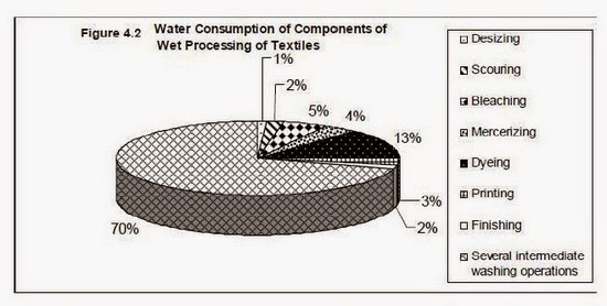
The production of textile goods involves spinning (fiber to yarn), weaving / knitting (yarn to fabric), chemical (wet) processing, and garment manufacturing. The majority of the water consumption (72%) takes place in the chemical (wet) processing of textiles. The water is required for preparing the fabric for dyeing, printing and finishing operations, Intermediate washing / rinsing operations and machine cleaning.
Other major uses of water in the textile industry:
- Steam generation (boiler feed water)
- Water treatment plant (reject stream, periodic cleaning of reverse osmosis plant,regeneration and washing of demineralization, softener plant, back wash of media filters);
- Cooling (processing machines, cooling tower);
- Humidification (spinning process); and
- Domestic purposes (irrigation of lawn and garden, sanitation, cleaning, drinking and miscellaneous uses).
Textile dyeing industries need huge quantity of water for textile dyeing, which they normally pump out repeatedly from the ground or natural water sources resulting in depletion of ground water level.
 |
Based on the above mentioned fact “SSP” has developed a technology which can process such harmful toxic effluent water and transform it into reusable water. Thus the textile industries will have the advantage of using the same water in the dying process repeatedly, also the salt used for dyeing can be reused or sold in the market. The technology offered by SSP can overcome all problems pertaining to environmental pollution in respect to textile dying industries.
Need of ETP:
Water is basic necessity of life used for many purposes one of which is industrial use. Industries generally take water from rivers or lakes but they have to pay heavy taxes for that. So its necessary for them to recycle that to reduce cost and also conserve it. Main function of this ETP is to clean GCP effluent and recycle it for further use.
The basic thrust of the technology is to convert entire quantity of effluent to zero level by separating water and salt using evaporation and separation technology. The concept and the treatment is based on the removal of the entire COD/BOD and the condensate coming out to meet the fresh water quality requirement in the process.
Effluent Generation and Characteristics:
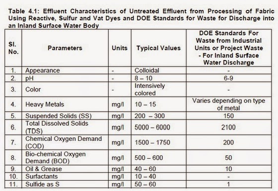
Wet processing of textiles involves, in addition to extensive amounts of water and dyes, a number of inorganic and organic chemicals, detergents, soaps and finishing chemicals to aid in the dyeing process to impart the desired properties to dyed textile products. Residual chemicals often remain in the effluent from these processes. In addition, natural impurities such as waxes, proteins and pigment, and other impurities used in processing such as spinning oils, sizing chemicals and oil stains present in cotton textiles, are removed during desizing, scouring and bleaching operations. This results in an effluent of poor quality, which is high in BOD and COD load. Table 4.1 lists typical values of various water quality parameters in untreated effluent from the processing of fabric using reactive, sulfur and vat dyes and compares these to the DOE effluent standards for discharge into an inland surface water body (e.g. river, lake, etc.). As demonstrated, the effluent from textile industries is heavily polluted.
 |
 |
Textile industries (fabric dyeing and chemical treatment industries) are classified according to the Environmental Conservation Rules 1997 as Red category industries, and therefore an ETP must be designed and constructed to treat plant effluent. The effluent from the plant must meet the national effluent discharge quality standards, including the “Quality Standards for Classified Industries”, before discharge to the environment. These quality standards must be ensured at the moment of beginning trial production. The waste discharge standards differ according to the final disposal place of the effluent. The effluent standards are presented in Tables 4.3 and 4.4 (also included in Part 1). It is the DOE’s mandate to enforce this legislation, and this guide provides the tools required to assess the ETPs proposed by textile industries in the EMP/EIA.
Discharge Quality Standard for Classified Industries:
 |
There are generally four levels of treatment, as described below:
- Preliminary: Removal of large solids such as rags, sticks, grit and grease that may result in damage to equipment or operational problems (Physical);
- Primary: Removal of floating and setteable materials, i.e. suspended solids and organic matter (Physical and Chemical);
- Secondary: Removal of biodegradable organic matter and suspended solids (Biological and Chemical);
- Tertiary: Removal of residual suspended solids / dissolved solids (Physical, Chemical and Biological)
- A properly designed biological treatment plant, which typically includes screening, equalization, pH control, aeration, and settling, can efficiently satisfy BOD, pH, TSS, oil and grease requirements. However the compounds in industrial effluent may be toxic to the microorganisms so pretreatment may be necessary. Most dyes are complex chemicals and are difficult for microbes to degrade so there is usually very little colour removal.
- Another option is a physico-chemical treatment plant, which typically includes screening, equalization, pH control, chemical storage tanks, mixing unit, flocculation unit, settling unit and sludge dewatering. This type of treatment will remove much of the colour depending on the processes used. It can be difficult to reduce BOD and COD to meet effluent standards and it is not possible to remove TDS.
- Most often, physico-chemical treatment will be combined with biological treatment. The typical components of such a plant are screening, equalization, and pH control, chemical storage, mixing, flocculation, primary settling, aeration, and secondary settling. The physico-chemical treatment always comes before the biological treatment units. Using a combination of treatments will generally reduce pollutant levels to below the discharge standards. 4-8
- Another form of biological treatment is the reed bed, which can be used with a settling tank, or in combination with other treatment processes It presents a natural method of treating effluent which is often lower in capital, operation and maintenance costs. Reed beds can contribute to a reduction in colour, a decrease in COD, an increase dissolved oxygen and a reduction in heavy metals, but function best with some form of pretreatment.
Overview of Stages in ETP Assessment Procedure:
Shows the ETP assessment procedure. There are 3 stages for reviewing an ETP design and checklists are provided for each. As indicated, in any stage if the information provided for the proposed ETP is found to be inadequate, incorrect or outsidethe guideline values, the industry must be consulted to provide or correct the
information.
 |
 |
Description of Effluent Treatment Plant Process Sequence in Textile Industry:
Cooling & Mixing:After primary filtration, the liquor passes to cooling and mixing tank in which uniform mixing of effluents from various process takes place. A paddle mixer is provided for mixing. Cooling of the effluent may be done with the help of cooling tower.
Neutralization:
The effluent is pumped to a tank in which it is neutralized by acid or alkali dozing. The tank has an automatic dosing controller which at automatically control the dose of acid or alkali to maintain the required PH .
Co-Agulation:
Then the effluent is pumped to the co-agulation tank. Chemical co-agulation very effective for removal of color and suspended materials, aluminum, ferrous sulphates, ferric chloride, chlorinate dcopper etc. to increase the efficiency of co-agualtion, co – agulation gain may be added for example polyacrylate.
Setting & Separation of Sludge:
Some of the soluble organic matter and light suspended solids will form a blanket of flocculent matter with the co-agulants. The blanket is skimmed of to another tank and the remaining solution is moved to pressure filter.
Pressure Filter:
For pressure filtration vacuum pumps may be used to force through the filter and suspended flocks are collected in the pressure fine filter.
Discharging to Drain:
After filtration the purified water sent to drain which eventually reach to the river or anywhere else.
Process Diagram o ETP:
 |
The purpose of launder is to flow the effluent of gas scrubber to distribution chamber Inlet channel is designed for a surge flow of 1950m3/hr @ slope of 2% so water flows at 1.5m/s(self cleaning velocity).Self cleaning velocity is that velocity at which if the sludge flows it will not get accumulated in the launder.
2. Distribution on chamber:
Purpose of distribution chamber is to divide the flow (design flow of 1140m3/hr) into two equal flows. In case if one of the thickener is closed then there would be no distribution so selection of pipes is done on this criteria. The size of gates is designed such that there is equal distribution always.
3. Flash Mixer:
There are two flash mixers designed for a flow of 1140m3/hr with a retention time of 60 sec. So its volume must lie around 19m3. In flash mixer alum (coagulant) acts upon sludge so that suspended solids settle down. In addition pH of sludge is also raised by lime as it is required to have a pH of 7-9. Polyelectrolyte (flocculants) also acts upon to fasten the process of coagulation.
 |
| Pic-Flash mixer |
Al2 (SO4)3.12H 2 O 2Al3+ + 3SO42- + 12H2O
SO42-+H2O HSO4-+ OH- (Cause pH change)
Ca (OH) 2 Ca2+ + 2OH- (Cause pH change)
The basic water causes Al(OH) 3 to precipitate bringing small particles with them and then making water clear. Fe2O3 is removed mainly by coagulation. The polyelectrolyte makes big lumps of the coagulated particles so they settle down.
 |
| Chemical dosing |
The clarifier separates the treated slurry from clean water. The sludge settles down and cleans water at the top flows down to the cooling tower from where it is cooled and recycled. According to PG the SS content in this water must not be greater than 100 ppm. The clarifier has a racker arm which extracts the sludge out of clarifier. In case if sludge height goes higher than the racker arm then it will automatically lift up and then settle down taking sludge with it. From here sludge is pumped to sludge tank.
 |
| Pic- Clarifier |
Suspended Carrier Tank:
In the first tank, organisms are grown on the inside of special plastic rings. This tank performs most of the treatment. The organisms appear as a thin brown film on the rings.
 |
In the sludge tank the sludge is continuously agitated in order to prevent settlement of sludge. Each tank has capacity of 224m3 and can hold for 8 hrs. Main purpose of the tank is to hold sludge for transfer to filter press. From sludge tank the sludge is pumped to filter press by filter press feed pump. In the second tank organisms which are suspended in the tank perform the rest of the treatment. The organisms are very small and appear as a fine brown sludge (called Activated Sludge) in the tank.
 |
| Sludge tank |
The third tank is a clarifier in which the suspended organisms are separated from the treated effluent by settling. The settled organisms are pumped back to the second tank to keep them in the system.
 |
| Pic- Secondary Clarifier |
Sludge from the sludge tank will be pumped to the Filter Press equipments for dewatering purpose. According to performance guarantee the cake moisture should not be more than 20%. For this purpose different types of filters are used namely- gravity setters, gravity belt filters, centrifuges, vacuum or pressure belt filters and filter press. But among these filter press is most efficient and economical. Other filtration systems offer high pressure filtration, but only the filter press has both high pressure capability and efficient filter cake removal. The filter elements are constructed of lightweight polypropylene. They are extremely corrosion resistant and virtually eliminate plate breakage.
 |
| Pic- Filter Press |
 |
The treated effluent from the clarifier is further treated by flocculation with chemicals followed by Dissolved Air Flotation. This step polishes the effluent before discharge to the river.
 |
Dewatering is accomplished by pumping a slurry or sludge into chambers surrounded by filter membranes. As pumping pressure is increased the filtrate is forced through the accumulated filter cake and membrane until the chamber is full of solid filter cake. The chambers are formed by two recessed plates held together under hydraulic pressure. The hydraulic ram moves the follower against the stack of filter plates closing the press. The ram continues to apply sealing pressure of sufficient force to counteract the high internal compaction pressures.
The head stock and tail stock are held in place by specially engineered side rail support bars. The filtrate passes through the membrane and is directed by channels in the plates and drain ports to the head stock for discharge. The filtrate typically contains less than 15 PPM suspended solids. The filter cake is easily removed by simply reversing the hydraulic ram, thus opening the press. The lightweight plates may then be moved apart, permitting the compacted cake to fall from the chambers. Higher the internal pressure, the greater the solids compaction. The standard press is constructed to withstand 100 PSI compaction pressure producing a hard dry cake. The special high pressure press can withstand 225 PSI for sludge more difficult to dewater.
Ozone Treatment for Textile Effluent Treatment Plant COD, Colour Removal Ozone Wastewater:The use of ozone in textile effluent treatment appears to be a very attractive alternative with considerable application potential. Ozone is a powerful oxidizing agent when compared with other well knows oxidizing agents. Ozone is capable of causing the degradation of dyes.
Advantages of Ozone Generator in Textile Industry Effluent Treatment Plants:
- Ozone reduces COD.
- Ozone reduces BOD.
- Ozone removes Colour.
- Ozone eliminates Odour.
- Ozonation increases the biodegradation effectiveness.
- Decomposes rapidly, leaving no harmful byproducts.
- Increase efficiency of Filter.
- Due to its unstable physical property, it should be generated at the point of application for use in treatment purposes.
- After chemical oxidation residual ozone reverts to oxygen.
- Environment friendly gas.
- Can be retrofitted to existing and new treatment plant.
- Low operating cost.
- Easy to operate & handle.
 Posted in: Wet process


.jpg)


0 comments:
Post a Comment